
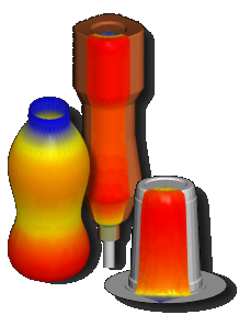
B-SIM example
Here is one example used in the design of a part produced by extrusion blow molding.
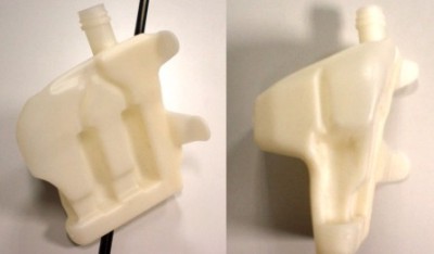
Water tank - Design optimization
In this example a design of a water tank, used in cars, was optimized. The minimum required final wall thickness was 0.8 mm. Moreover, the tank had to fit into the space in the car. The figure below shows the molded part. The tank has hollows on one of its sides, planned to hold a pump and a filling sensor. At the top, there is an opening for filling up. The part is made from HDPE.
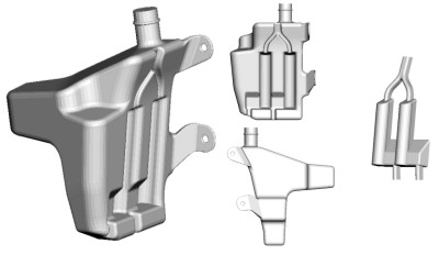
The following figure on the left shows a CAD model of the tank as it was designed to fill the available space in the car. The model was created from IGES file, delivered by the car producer. On the right, there is a movable part to form the hollow for a pump and a sensor. This part is represented by a stand-alone tool in B-SIM.
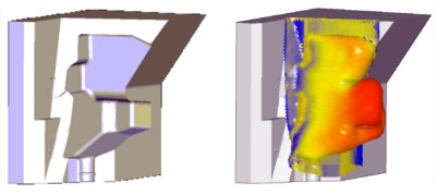
The first simulation was performed without the movable part forming the hollows. The result of this simplification is a large web, see the figure below.
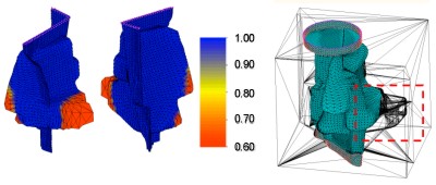
The web creation was elliminated by a small shift / modification of the dividing surface. Results of the new simulation allowed analysis of the minimal thickness. On the following figure in presented, the thickness scale was set to a range from 0.6 to 1.0 mm in order to highlight the critical areas. On the right, there is also marked an unfilled area, where the part was not formed completelly.
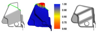
Using the color scale, the area with the critical thickness can be easily determined. Along the border wall thickness 0.8 mm, a trim line is assigned. The figure below shows (from the left to the right) original part geometry, simulated wall thickness and modified geometry with removed parts with too thin walls.
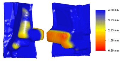
The design of the tank was modifed in CAD and transfered back to B-SIM. The result of simulation with the modified part geometry is shown in the following figure. It is obvious the final wall thickness does not go below the critical value 0.8 mm.
The last step is simulation with the movable part forming the hollow for the pump and the sensor. Once the mold is closed, this part moves into the mold cavity and forms the hollow. Three steps of the movement are shown in the figure bellow:
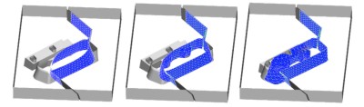
This simulation proved that the final wall thickness satisfies the criterion of the minimal thickness 0.8 mm even when the extra movable part is used. The usage of this movable part works very good when this part is moved into the mold cavity once the mold is closed.In this example, the final part geometry was optimized and the results were used in modification of the original tool design.
Without this simulation study, the original part would have to be modified several times or even manufactured once again to achieve a design satisfying the criterion of the minimal thickness. When the real costs are compared, the computer simulation is about 1/6 of the cost of the mold in this case. Moreover, the time spent for simulation is negligible when compared with time needed for the mold modifications (if such modifications are necessary). This means that using a simulation software in design optimization saves time and money.
This example is taken from PhD thesis Prozess-Simulation des Extrusionsblasformens von Kunststoffhohlkörpern (Process optimization of extrusion blow molded hollow plastics parts, Peter Gust, Fachbereich Maschinentechnik der Universität Siegen.